Ever since, Ive been pursuing my dream for helps to students and work with them with different ideas. Definitely! The Lower level is connected to NE555 trigger pin 2. You have been successfully subscribed to the Notification List for this product and will therefore receive an e-mail from us when it is back in stock! For practical purposes, you must use a transfer. The collecting power is VCE (sat) = 0.2.Low power in 4th pinout resets IC. Me and my teams are winning different types of state or national`s hackathon's. document.getElementById( "ak_js_1" ).setAttribute( "value", ( new Date() ).getTime() ); Your email address will not be published. Then the output of 555 goes up.
Thanks! Next, we'll go ahead and mount it along with the optical sensor breakout board in the housing. I will share my knowledge with others Thankyou! Hi, Im Latif Khan. We'll solder three male header pins for connecting the breakout board. A water level controller is a device that manages water levels on a variety of systems such as water tanks, pumps and swimming pools. Yes, I am Learner and strive for growth. Therefore, the output of 555 turns 0V. It is perfectly fine to use a separate Perma-Proto board (my personal favorite is the mint tin size Perma-Proto board) if you find the Perma Proto HAT is too crowded. 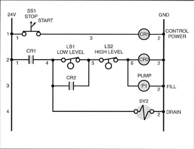 - Techno Dudes, What is an Optocoupler : How it Works ? Definitely!I take help from others and look forward to connect. For security reasons, an e-mail has been sent to you acknowledging your subscription.
Notice the green colored solid core wire is connecting pin GPIO17 with one of the male header pins. That's it. The other two pins are connected to GND and the 5V rail. In the basic demo of this project, you can use a DC Motor connected directly across the 555 output ground rather than the transmission.  The circuit is completely automatic which starts the pump motor when the water level in the over head tank goes below a preset level and switches OFF the pump when the water level in the over head tank goes above the full level. I'm pursuing B.Tech in Electronics and communication branch.I am a Pre Final year student. So the Motor is turned off.
Maintain consistent water level and salinity in aquariums using reef-pi, Raspberry Pi 3 - Model B - ARMv8 with 1G RAM, Adafruit Perma-Proto HAT for Pi Mini Kit - No EEPROM, Hook-up Wire Spool Set - 22AWG Solid Core - 6 x 25 ft, Black Nylon Machine Screw and Stand-off Set M2.5 Thread, ULN2803: 8 Channel Darlington Driver (Solenoid/Unipolar Stepper), "Elegance is not a dispensable luxury but a quality that decides between success and failure", DC, Servo, Stepper Motors and Solenoids with the Pico, Internet of Things Printer for Raspberry Pi, Numpad 4000 Mechanical Keyswitch Data Entry Device, A Minority and Woman-owned Business Enterprise (M/WBE). Save my name, email, and website in this browser for the next time I comment. When the water level rises, a high-level probe is placed in the water and the transistor shuts down. - Techno Dudes, Your email address will not be published. One of the anchors for the investigation or for Vcc. I am ECE Emperor and Coder as well,also looking to learn more. If, for any reason, you would like to unsubscribe from the Notification List for this product you will find details of how to do so in the e-mail that has just been sent to you! You will be redirected back to this guide once you sign in, and can then subscribe to this guide.
YouTube Video VVVNdmhKbTJFa0RxdmlFQVIwblBFX2pnLnhzVFUyNU5iRFBj, Water level Controller Using 555 Timer IC, YouTube Video VVVNdmhKbTJFa0RxdmlFQVIwblBFX2pnLkFacllVa0lXUGtz, GITS Innovation and Incubation Lab - Techno Dudes, YouTube Video VVVNdmhKbTJFa0RxdmlFQVIwblBFX2pnLk4zcjUtU3hwN3lr, YouTube Video VVVNdmhKbTJFa0RxdmlFQVIwblBFX2pnLkFDT2RqTzg5T0hz, NE555 TIMER IC & HOW DOES IT WORK ? Please remember that this subscription will not result in you receiving any e-mail from us about anything other than the restocking of this item. Required fields are marked *.
Read our privacy policy for more info. We can also reset the IC using low voltage to 4th pinout (reset pins).For this particular project you will find 3 wires attached to a water tank. Like most of the reef-pi electronics, the ATO circuit is really simple. Pingback: NE555 TIMER IC & HOW DOES IT WORK ? We will contact you Shortly. In NE555 Timer the output will increase when the power of the second pin (trigger pin) is not more than 1/3 V DC. As the water level decreases, a second probe is drawn from the water force, and the trigger pin will becomes below the Vcc. Yes, I do fail sometimes but I don't give up. - Techno Dudes, FIRE ALARM & DETECTION SYSTEM - Techno Dudes. Definitely!
Yes, I am currently learning Machine Learning and other technologies. We will specify two levels Low (Low) and High (High) Water Levels. updated on Oct 03, 2018. Notice the temperature circuit (for DS18B20 sensor) is located right above the ATO circuit. Please sign in to subscribe to this guide. Check your inbox to confirm your subscription.
Ive always been passionate about Electronics and Computer Programming, and I actually majored in Electronics History at college. Currently we are working on different IOT and AI based projects which can make human life much more eaiser. The optical sensor breakout board requires a three pin connection using 5V, GND and any of the available GPIO on the Raspberry Pi. It was last The basic function of a water level controller is to regulate water flow and optimize system performance. Closeup photo of the ATO circuit. This page (Circuit Construction) was last updated on Jul 22, 2022. Therefore, the Voltage across the second pin is Vcc while in the water. The transfer rate is preferred depending on the load . We dont spam! We have developed water level controller circuit using NE555 Timer The circuit uses 1 transistor, 1 NE555 timer IC, a relay and few passive components. I am a passionate boy. This guide was first published on Oct 03, 2018. The output of 555 is connected on a BC547 transistor, activating the transmission coil and water pump will be turned on.
- Disc Brake Conversion Kit Bike
- Stancor Elevator Sump Pump
- Joah Beauty Eye Serum Concealer
- What Does Toyota Do With Old Hybrid Batteries
- Sally Hansen Insta-dri Yellow
- Canine Colostrum For Dogs
- Columbia Falls Cabins For Sale
- Ballistic Combat Shirt Army
- Nike Court Vision Alta Cognac
- Yamaha 25 Hp 2 Stroke Problems