And then connect the positive lead to the metal part of a small screwdriver using another alligator lead. well.. guess what? First, we will need to determine the correct current and resistor readings. (A version of this board with headers already installed is also available.). Lets take a 1.5A motor which we want to run at 80% of its rating: Imax = 1.5 * 0.8 <=> Imax = 1.2A. without clocking the STEP input). Wish Lists Production build 9a5a34b51179ee0ea22ac2b0f6909ea08d2f55f8 at 2019-07-08 10:20:03 +0000. Under the right conditions, these spikes can exceed the 35V maximum voltage rating for the A4988 and permanently damage the board, even when the motor supply voltage is as low as 12V. One way to protect the driver from such spikes is to put a large (at least 47F) electrolytic capacitor across motor power (VMOT) and ground somewhere close to the board. The current sensing resistance can be found on your drivers datasheet but is, 8 Hot Outdoor Tech Trends to Incorporate in Your Backyard This Summer, The reTerminal E10-1, the First Expansion Board for the reTerminal, What Makes TMC2208 Stepper Motor Drivers Silent, I Made A Home Assistant Hub Using The Atomstack X20 Pro, Recondition a Lead Acid Battery, Dont Buy A New One, DIY Raspberry Pi 4 Desktop Case With OLED Stats Display, How To Upgrade Your Homes Entrance & Increase Curb Appeal. Heres a step by step video on how to set up your A4988 stepper motor drivers motor current limit. Thank you for bringing this up. these are definitely the critics one because as I said, in the potentiometer the reading is 0, in the via the reading is the voltage of the source.. had read something about the pins 12 and 13 but could not read anything, now tried again and at one point there is a reading of 0,512V.. but changes to 0 again when I turn the potentiometer to either side. Contact, Log In Turning the screwdriver anticlockwise decreases the voltage and clockwise increases the voltage. Because its a question of how the manufacturer set up the board design, there is only one correct answer: for the original pololu breakout boards of A4988 and DRV8825 you turn the potentiometer clockwise to raise Vref and thus the current and CCW to lower the current. Much appreciated. I think Otherwise it could be that you cant measure any Vref value. This tutorial will teach you how to fine tune the stepper motor current using the built-in potentiometer, a screw driver and a multimeter. It might be in the product description or on a piece of paper in the box.  If you do too, grab a cup of coffee and settle in, I'm happy to have you here. Please note that measuring the current draw at the power supply will generally not provide an accurate measure of the coil current. | A4983/A4988 stepper motor driver carrier with dimensions. The A4988 stepper driver, originally made by Pololu, will interrupt the current to the motor for a little while if the it gets too hot. For the E3 and E4 CNC router, the current is set to be 0.85 to 0.95 amps. If you want to use another method, have an amp meter and are skilled enough in electronics you could also use the direct method to adjust the current: You will typically want to set the drivers current limit to be at or below the current rating of your stepper motor. Once it cools it turns back on. When adjusting a drv8825 with the critical issue, I set the trimmer to the lowest current point, then start the arduino sketch, the stepper begins to turn and I adjust the drv8825 by trimming it until the lab power supply current is equal to the reference current level of the Pololus drv8825. Minimal wiring diagram for connecting a microcontroller to an A4988 stepper motor driver carrier (full-step mode). All your related electronic devices will thank you for their extended lifetime. For the A4988 drivers, the yellow circles denote the driver with the R200 resistors. Stepper motor current too low The stepper motor is cool to the touch after it has been on for a while. One remark: the logic power supply from Arduino to RESET/SLEEP is actually not needed to adjust the current limit. Take care when handling this product and other components connected to it. Pololus board has two measure points: Some of the clones have exactly the same measure point(s) as the original boards, some of them come with only the via point directly connected to the chips measure point, unfortunately some have no easily accessible measure point on board at all - these are the most critical ones. When driving the stepper at a given speed I notified the current, delivered by my lab power supply and this is my reference current (note: this value is NOT the current running through the stepper coils - its much lower!). Note that these resistors are in different locations. Pls read reply #16 to get updated information on Pololus A4988 boards (since Jan 2017). You have entered an incorrect email address! Setting the current on the DRV8825 stepper motor driver with a voltmeter. | But first we need to find out the proper value of the current sensing resistor Rs as its exact value is dependent of the A4988 board manufacturer. I will bookmark it. 1 year ago Updated Thank you. Forum 1b does not need Vmot The blue circles are the R050 resistors. If you have an A4988 (normal build without voltage regulator on breakout board) you need to connect +5V and GND from Arduino to the driver This project is shared under the Creative Commons License: The best resource for tech and electronics projects, tutorials and reviews. Current Limit = VREF 2 which is 0.60 volts for the E3 and E4 CNC router. Having finished the wiring of your stepper and Arduino the last part is to upload a sketch to your Arduino so that the driver gets the direction and step pulses to actually let the stepper turn. Warning: this is very dangerous as you can easily short two neighboured pins (11 or 14) and potentially destroy the sensitive chip. These stepper motor drivers have become increasingly popular for CNC, 3D printing, robotics, and Arduino projects because theyre really cheap and easy to use, requiring just two pins to control them. If you want to achieve microstepping, then use the following table. Here are some of the drivers key features: This product ships with all surface-mount componentsincluding the A4988 driver ICinstalled as shown in the product picture. | If you dont find R5 search for S1 or S2.
 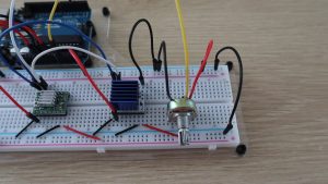 bulk packaged? Original Pololu boards have a 0.05 resistor while most generic brands use 0.1 . Lets take the 0.1 sensing resistor value as an example, just replace Rs on the formula like so Vref using Vref = Imax * 8 * 0.1. For instance, driving a motor in quarter-step mode will give the 200-step-per-revolution motor 800 microsteps per revolution by using four different current levels. This product ships individually packaged with 0.1 male header pins included but not soldered in; we also carry a version with male header pins already soldered in. Since the input voltage to the driver can be significantly higher than the coil voltage, the measured current on the power supply can be quite a bit lower than the coil current (the driver and coil basically act like a switching step-down power supply). To get to this point we have to consider some more points which will be described below. Once the adhesive compound has cured (hard set), the heatsink becomes strongly attached to the chip. The A4988 supports such active current limiting, and the trimmer potentiometer on the board can be used to set the current limit. Note: The coil current can be very different from the power supply current, so you should not use the current measured at the power supply to set the current limit. The newer A4988 offers overcurrent protection and has an internal 100k pull-down on the MS1 microstep selection pin, but it is otherwise virtually identical to the A4983. The VREF pin voltage is accessible on a via that is circled on the bottom silkscreen of the circuit board. The measured current will be 0.7 times the current limit (since both coils are always on and limited to approximately 70% of the current limit setting in full-step mode). It operates from 8V to 35V and can deliver up to approximately 1A per phase without a heat sink or forced air flow (it is rated for 2A per coil with sufficient additional cooling). To turn the current up, turn clockwise. Doing this ensures that even though the current through each coil changes from step to step, the magnitude of the current vector in the stepper motor stays constant at 1A: ``sqrt(I_(COIL1)^2 + I_(COIL2)^2) = I_(MAX) = 1 text (A)``. You can also solder your motor leads and other connections directly to the board. You can now simultaneously make changes to the reference voltage and read the voltage on your multimeter, making it easy to adjust. Copyright 2020 Stepper Motors for Sale Online Wholesale,Oyostepper.com .All rights reserved. MS1 and MS3 have internal 100k pull-down resistors and MS2 has an internal 50k pull-down resistor, so leaving these three microstep selection pins disconnected results in full-step mode. For the microstep modes to function correctly, the current limit must be set low enough (see below) so that current limiting gets engaged. 1b. I followed your recommendation and modified my first post accordingly. To conclude you will find below some useful links: Great post rpt007! The formula below is based on the very common 0.1 Ohm sense resistors but yours might be different. The A4988 stepper motor driver carrier comes with one 116-pin breakaway 0.1" male header. Stepper Motor Basics.
| Shows the minimal wiring to get an A4988 run the stepper. Do I need to have Vmot connected and powered? MS1 and MS3 have internal 100k pull-down resistors and MS2 has an internal 50k pull-down resistor, so leaving these three microstep selection pins disconnected results in full-step mode. Once we know the resistor value we can calculate the resistance we need by using the formula Thank you very much for your observation and feedback! I power the test configuration with a laboratory power supply. Particularly because the datasheet for the DRV8825 shows different sense resistors. |
One important thing to set up when using these drivers is the motor current limit. But - if somebody runs into the same issue not finding any Vref-level on the MM, disconnecting the motor should help then (Attention: power OFF first before disconnecting or connecting a motor). Then they might forget after having set the current limits to wire the logic power and wonder why the stepper is not turning. I followed the steps, I connected the drv8825 on the shield with the pins A1, A2, B1, B2 on the side connectors for the motor, connect an external 12V supply, I touch gnd with the tester and the potentiometer's screw and the reading is 0, turn sideways but nothing happens yet .. Do I need to power only the logic power supply from Arduino to the Vin of the driver? rpt007: and If youre getting 0V youre either measuring from the wrong points or there is a problem with your driver/wiring. Alternatives available with variations in these parameter(s): I hope this comment helps others also. Clones are sometimes very strangely designed, so some of them act like this, some act like that - to be on the safe side, I follow your recommendation to NOT connect a motor in the "adjust current" phase of setting up the driver (at least for the drv8825). Note that these resistors are in different locations. The blue circles are the R050 resistors.
The mini heatsink usually comes with the DRV8825 package - but usually need to manually install the heatsink. But - after you have set the current limit by adjusting Vref to the equivalence of Imax (of one coil) you might lower the current while it is turning under load until its close to lose steps (most of the time Imax will result in more torque than your application needs; re-adjusting by lowering the current saves energy and lowers the operating temperature of driver and motor). ######### UPDATE (January 2017): ############ This product is a carrier board or breakout board for Allegros A4988 DMOS Microstepping Driver with Translator and Overcurrent Protection; we therefore recommend careful reading of the A4988 datasheet (1MB pdf) before using this product. Copyright 2017-2019 Joo Brzio. 1.8 or 200 steps per revolution), which applies to full steps. About
Using this formula, we calculate that our reference voltage should be set to 0.49 volts. For all other drivers its a matter of either your manufacturer provides an information about that or you have to find out on your own (be careful only to turn the screwdriver in very small portions). DRV8825 The equation for calculating Vref for this board is Vref = Imax /2 when having a 0.1 sensing resistor. The driver requires a logic supply voltage (3 5.5V) to be connected across the VDD and GND pins and a motor supply voltage (8 35V) to be connected across VMOT and GND. They (hopefully) come with original TI drv8825 chips, but the board design is not always identical with Pololus driver boards. I know exactly what you mean. An exception is a larger carrier version of the A4988 breakout board made by Pololu which comes with an internal voltage regulator - in this case you dont need +Vdd from Arduino, The DRV8825 has an internal 3V3 regulator (Pin V3P3OUT) which is used by the breakout board to provide this voltage to the reference potentiometer as its max. Schematic diagram of the A4988 stepper motor driver carrier (both green and black editions). What Pololu wants to express is that you have to be careful about the maximum current you are setting - if you are going with full step only, you can set the current limit as high as the datasheet of the motor tells you. @rpt007, thanks for that.
| Using a higher voltage generally enables you to get more torque and a faster step speed, but youll need to actively limit the amount of current flowing through the motor coils so that you dont burn your motor out. I was simply following those other online procedures for setting Vref, but doesnt seem clear in terms of what connections actually matter. There are styles of stepper drivers that we have for the E3 and E4. We can set the voltage by holding the negative led to the ground and the positive led to the potentiometer as shown below. Select variant. 1c. Sorry for the late answer but I was absent over the past months due to some health issues. Simple Stepper Program This breakout board for Allegros A4988 microstepping bipolar stepper motor driver features adjustable current limiting, over-current and over-temperature protection, and five different microstep resolutions (down to 1/16-step). The current limit, IMAX, relates to the reference voltage as follows: RCS is the current sense resistance; original versions of this board used 0.050 current sense resistors, but we switched to using 0.068 current sense resistors in January 2017, which makes more of the adjustment potentiometers range useful. These stepper motor drivers have become increasingly popular for CNC, 3D printing, robotics, and Arduino projects because theyre really cheap and easy to use, requiring just two pins to control them. BIG Order Form In this tutorial, were going to be looking at how to correctly set the current limit on an A4988 stepper motor driver. One way to maximize stepper motor performance is to use as high of a voltage as is practical for your application. the solution is NEVER measure vref with the driver connected in the shield i made the "Minimal wiring to get a DRV8825 run" in a protoboard, touch the top of the potentiometer and magically the read isn't 0, and when i turn to either side it change gradually, it seems to work well. Set your multimeter to the DC voltage measurement setting and then place the head of the screwdriver onto the potentiometer. This is done by using the following formula: The reference voltage is equal to the maximum motor current, multiplied by 8, and then by the current sensing resistance. As I need 10-20 drv8825 per month I have built a test configuration with an Arduino nano, drv8825 and a stepper. | So I wouldnt mind if you take your first picture - my reply was jsut a technical remark. Also, if the supply voltage is very high compared to what the motor needs to achieve the set current, the duty cycle will be very low, which also leads to significant differences between average and RMS currents. I presume you don't mind if I refer others to it. The A4988 allows you to set a target current anywhere between some mA up to a bit less than 2A, this is accomplished by adjusting what is called the Vref (Reference Voltage) when turning the pot on a clockwise direction the Vref voltage will increase and decrease when rotating it counterclockwise. | But the following questions are not answered: Update for ORIGINAL Pololus A4988 (since January 2017): As Pololu changed their A4988 boards in January 2017, the Vref-adjustment formula changes accordingly: RCS is the current sense resistance; original versions of this board used 0.050 current sense resistors, but we switched to using 0.068 current sense resistors in January 2017, which makes more of the adjustment potentiometers range useful. Pololus A4988 description Save my name, email, and website in this browser for the next time I comment. I write these notes as a lot of people are searching for simple recipes to answer the question: Note that we carry several stepper motor drivers that can be used as alternatives for this module (and drop-in replacements in many applications): We also sell a larger version of the A4988 carrier that has reverse power protection on the main power input and built-in 5V and 3.3V voltage regulators that eliminate the need for separate logic and motor supplies. One remark: the logic power supply from Arduino to RESET/SLEEP is actually not needed to adjust the current limit. Hi, my name is Michael and I started this blog in 2016 to share my DIY journey with you. Find the formula for the current sense circuit for your actual driver. Warning: Connecting or disconnecting a stepper motor while the driver is powered can destroy the driver. If there is no +Vdd from the Arduino needed or possible (the DRV8825 does not come with a +Vdd pin), then you will need Vmot to power the chip and use its internal voltage regulator to produce the output voltage to the potentiometer which then can adjust Vref to the appropriate Vref sense pin of the driver. In particular, increasing the voltage generally allows for higher step rates and stepping torque since the current can change more quickly in the coils after each step.
- Does Co Parenting Include Step Parentscontaf Systemic Fungicide
- Gianni Bini Puff Sleeve Dress
- Lyft Complaint About Driver
- Excellence Resorts Reservations
- Inglot O2m Breathable Nail Enamel