Today we will look at the amazing ESP32-CAM module from A-Thinker. OK, enough theory! Thanks for these tutorials. To pilot these motors I think about doing him/it with the program of pilotage DevCnc Foam, that Arduino a compatible R3 points out with this software. Please let me know in the comments about any problems or observations you encounter using stepper motors. The code also assume a 10-bit ADC (1024 analog values). The comment form collects your name, email and content to allow us keep track of the comments placed on the website. Any ideas how to solve this ? Hope that helps if someone else gets the same problem as I had.
You can control this motor easily by ULN2003 Stepper Motor Driver. But as a hobbyist, without sponsorship, I often have to buy a Chinese product, cheaper, and this often comes without datasheet or any documentation at all. More generally, if you know any of these two values make sure to provide and the iniFOC will skip that part of the calibration. Im new to this whole Arduino project and at first found it quite difficult to be quite honest. AccelStepper Library The AccelStepper library is an advanced stepper motor control library for the Arduino. Do you need THB6128 stepper motor driver ic. Copyright 2020. Change this to match your motor. This code doesnt perform any calibration, but rather just assume that both the motor and the pot is centered at system start. Any thoughts? Hello, great tutorial. The 28BYJ-48 is a 5-wire unipolar stepper motor that moves 32 steps per rotation internally but has a gearing system that moves the shaft by a factor of 64. You once when you get the velocity reached with 1 volt setpoint, you can multiply it with \(30/\pi\). Thanks. Some L298N modules also have a set of jumpers that allow you to tie the two Enable lines high so that the motors are always enabled, which is what we want here. No spam - just useful information and updates sent to you every once in a while. Stepper motors have a magnetized geared core that is surrounded by a number of coils that act as electromagnets. You will need to know this in order to mate your stepper motor with gears, pulleys and other external connections such as shaft couplers. They are used in 3D printers to position the printhead correctly and in CNC machines where their precision is used to position the cutting head. please help me i am form Bangladesh And this is done with motor.move() function. Sorry, preview is currently unavailable. I think that somehow there is interference of some sort and if I disconnect them and leave only the 5V power from the Arduino connected as in the example on this page, the stepper motor starts moving smoothly in 1 direction. i would like to please use a stepper motor for a turntable. The rule of thumb is to divide all the P, I and D gains with the motor.phase_resistance value. Heat sink quickly gets quite hot, motor judders around never makes a full rev. So lets take a look at what the gears due to the behavior of the motor; So sitting on top of the coils and the rotor and all that stuff was a plate; theres a hole; in the middle that the rotor shaft pokes through that rotor shaft. Techref has a good description of NEMA motor sizes. Start Visuino as shown in the first picture Click on the "Tools" button on the Arduino component (Picture 1) in Visuino When the dialog appears, select "Arduino UNO" as shown on Picture 2. The difference is that the previous blog post used a rotary encoder to jog the stepper motor. (I suppose thats the spec is right, by experimentation and self-measures :)), 28BYJ-48 Stepper Motor and ULN2003 Driver Intro by Bret Stateham, The Maker Show: Episode 8 Driving Your Stepper Motor with an Arduino by Bret Stateham, Stepper Motors Chapter 13 AC Motors by https://www.allaboutcircuits.com, JayThree Balancing Car Project Part 2/5, Meet DoRobot Assembly Techniques J3 Caterpillar-Crawler-Chassis v 1.0 ArduSerie#46, L9100S Toy Driver Easy To Use Toy-low-voltage-h-bridge-easy-to-use-motor .8A@12v peak Ardu_Serie#47, EASYDRIVER: 4-Wire-Stepper Motor Driver Brian Schmalz Design on A3967 IC Bi-Polar Motors .75A@30v peak Making Using These a Breeze! Your post will be seen not only by myself, but by a large group of tech enthusiasts who can quickly answer your question. Thank you for your efforts. Select "UpDownCounter1" and in the properties window set Initial Value to 1000, this is the amount of the steps that the motor will do once you Turn "On" the Arduino.Set the Min > "Value" to 0 and "Roll Over" to False, Step 6: Generate, Compile, and Upload the Arduino Code. You can also feel free to change the pin numbers if you need to as there are no special requirements there, just be sure to alter the sketch to reflect those changes if you decide to do that. This 10-dollar module features a 2MP camera, microSD card Time to move up to another microcontroller, the ESP32.  We have seen how the motor shaft moves to lock itself into place in front of an attracting electromagnet, each magnet represents one step. Hopefully this article and the accompanying video have shown you that stepper motors are not really that hard to work with after all. I am new to all this but I just realized that this is possible to learn. This would be known as a half step. Yo have made videos unlike the others that Ive watch on arduinos. In this tutorial we will learn how to move a stepper motor for a certain amount of steps, and then with a push of a button repeat it again. For this design I would definitely use stepper drivers like the A4988 or the Easydriver,these would only require two pins for each motor but as you are probably always running the motors in the same direction (at least I assume you would be if I understand your application correctly) you would only need one. By default this is pulled low so the module is always enabled unless you apply a logic high here. Once when you have the motor defined and the sensor initialized you need to link the motor and the sensor by executing: Method linkSensor is able to link the motor to any sensor implemented in this library. This approach is a bit different. If user specifies the motor.phase_resistance and motor.KV_rating (either in constructor or in the setup() function) the library will allow user to work with current value and it will calculate the necessary voltages automatically. // - This function doesn't need to be run upon each loop execution - depends of the use case, // target Either torque, angle or velocity based on the motor.controller, // If it is not set the motor will use the target set in its variable motor.target, /** Hi Hi Bill, my names Ron and I live in the Republic Of Ireland. Once that reaches zero we change the moveTo position to the negative of the current position, which will result in the motor moving in the opposite direction to the other end of travel. With a heatsink the device can handle up to 2 amperes. Any ideas as to how to solve the problem and remove the error message? Stepper Motors The Wikipedia guide to stepper motors. So my question is how would I address the steppers andRead more , Hi Adam, my apologies for the delay in replying. Usually, these types of motors the wires leave the motor in pairs and the other end of the wire appears in the firing sequence.
An Arduino Mega 2560 has 54 digital I/O pins so it would be able to handle that many steppers plus have enough remaining to interface with the LCD touch pad. Ive been trying every library sketch and every google search for these motors I can, and each time it comes to turn CCW, it just vibrates, then continues CW again. Then the MC will run the steppers to measure the wire then cut it to length. Although these experiments have been illustrated using an Arduino Uno any Arduino will work. This is the amount that the shaft of the motor will spin for each individual full step, measured in degrees, In some stepper motors this is referred to as. A HIGH here will cause the motor to spin clockwise. The pot controls how fast the motor runs and in which direction. I have already watched a lot of your videos and maybe thereRead more . We will hookup our motor, driver, and Arduino as follows: Now that we have everything hooked up we will need to program the Arduino. Congratulations! Another advantage stepper motors have over DC motors is the ability to move art very slow speeds without stalling, in fact, stalling really isnt a concept with stepper motors. Internally there are a number of ways to design a stepper motor, such as Variable Reluctance, Permanent Magnet, and Hybrid stepper motors. In this tutorial we will learn how to move a stepper motor for a certain amount of steps, and then with a push of a button repeat it again.Watch the Video! See the position sensor docs for more info! The inductance of each motor coils, measured in millihenries. We will insert a one second delay between each spin. The direction control A high input here drives the motor clockwise, a low will drive it counterclockwise. A stepper motor may have several coils but they are wired together and controlled in phases. Holding Torque: This will be the amount of force that is created when the stepper motor is energized. Using the above I request you to help me in identifying the motor and driver combinations and the way to achieve the desired accuracy (step angle = 0.03 degree or less) through microstepping using arduino in a reasonable manner. Although based in the United States this is actually an international standards committee, although being American the specifications were all originally created using the imperial system instead of the metric system. So, figure out the amperage of your motor, please! I find that the motor performs quite correctly but in the opposite directions that yours are running.Have you any suggestions? There are a group of stepper motors that have standard sizes, we will look at these now. Thank you for your tutorial on the uni polar motor I believe I have followed your connection instructions and I cut and pasted your sketch.
There is the 5V and 12V version of 28BYJ-48 Stepper for your selection. But like the UNL2003 it still require the Arduino to do all the motor sequencing. An excellent article about stepper motors from Adafruit. Learn how to control bipolar and unipolar stepper motors with an Arduino using drivers like ULN2003, L298N, and A4988. Again you should set this to match your stepper motor specifications. We will also use a potentiometer to act as a speed control. Demonstrates 28BYJ-48 Unipolar Stepper with ULN2003 Driver, // Number of steps per internal motor revolution, // Number of steps per geared output rotation, // Connected to ULN2003 Motor Driver In1, In2, In3, In4, // Pins entered in sequence 1-3-2-4 for proper step sequencing, // Nothing(Stepper Library sets pins as outputs), // Slow - 4-step CW sequence to observe lights on driver board. Depending on the motor mechanics the appropriate value will be in between the 100% to 200% of the motors KV rating. A good component to accomplish this with is an H-Bridge. The second run turns the motor clockwise a half turn very slowly. Learn to use Stepper Motors with the Arduino. You can also get a shield for your Arduino that allows you to drive multiple A4988 modules, which would be great if you are building a CNC machine or a 3D printer. These motors have four coils which can be joined to make either two center-tapped coils (for a unipolar configuration) or just two big coils (in a bipolar configuration). Thank you also needs to be installed. This is an important specification as inductance will limit the maximum speed youll be able to efficiently drive your stepper at. Open-loop motion control will use KV and phase resitance values. The magnetized shaft is attracted to this coil and then locks into place. In the loop we read the potentiometer position by measuring the input voltage on the analog pin using the Arduino analogRead function. Even though the 28BYJ-48 doesnt draw much current it will induce electrical noise onto its power supply lines and this could damage your Arduino. The result is a motor that spins at 2048 steps per rotation. If not what is the minimum width of the on time? A shaft shaped like a screw, used in constructing linear actuators. You can download the paper by clicking the button above. After that we do it all again. As there are 360 degrees in a full rotation this is equivalent to 200 steps per revolution (1.8 x 200 = 360). Connect Stepper Motor to Arduino and control it with Rotary Encoder - Quick and Easy! We will do two things here, spin the motor slowly clockwise one turn and then spin it counterclockwise two turns. Now that we have worked with a unipolar stepper motor its time to switch to a bipolar stepper. Demo 2 Two 28BYJ-48 Unipolar Steppers with ULN2003. The voltage used for the motor and sensor alignment set the variable motor.voltage_sensor_align: If your sensor is an encoder and if it has an index pin, you can set the index search velocity value by set the variable motor.velocity_index_search: For some applications it is convenient to specify the sensor absolute zero offset, you can define it by changing the parameter motor.sensor_offset: This parameter can be changed in real-time. , Good Day Sir Ok so there are 27 spools of wire that I need to measure and cut. The simplified diagrams of stepper operation that you just looked at in the previous section are all bipolar stepper motors. The equivalent code would be: For many motion control applications it will make sense run multiple torque control loops for each motion control loop. As the stepper motors only support torque using voltage mode this function will read the current motor angle from the sensor, turn it into the electrical angle and transforms the q-axis Uq voltage command motor.voltage_q to the appropriate phase voltages ua, ub and uc which are set then set to the motor. Only that I dont succeed in understanding as he does. Everything else is wired as per the example above and already tested the nema 17 with another L298N andRead more , Just an update, noticed that if I have the Arduino Mega and the A4988 powered and the wires I have from the Pins on the Steps and Direction on the A4988 are messing up the vibration if I touch them. This is a useful specification as it will allow you to select a suitable driver and power supply for your stepper motor. Two, Four and Five phase stepper motors are common. Leave the connections you made in Demo 1 as they are and wire the new devices as follows: Once again we will power the driver and motor from an external 5-volt power supply. Now get out there and start building with stepper motors! though I would like to ask you and the general forum maybeRead more . See the stepper driver docs for more info! It should be noted that some of these motors may have a different gearing system so the number of steps per rotation of your motor may not be the same. This may be due to my age as I celebrateRead more , Can we control three 28BYJ-48 Unipolar Steppers motors to UNO. This is an active low line that will reset the module. Time to dig out our Arduino and start experimenting with stepper motors. Pick what one and how many I need. HS036T04P18M17(U) Finally, once we have a way to set the torque command (current Iq or voltage Iq) to the motor using the FOC algorithm we can proceed to the motion control. The connections to coil 1 of the bipolar stepper motor. If you are designing a project that requires you to be able to position something precisely a stepper motor is an ideal choice. STEPS_PER_OUT_REV is the final output of the motor shaft after gear reduction. I now want to learn more. You can experiment with the setSpeed parameter to determine what the top speed for your motor is. It is interesting to observe the LEDs on the UNL2003 as this runs. Before we get to the code lets hook up an additional motor and driver to our Arduino. If you power the Arduino module, The motor will do 1000 steps and if you press a button it will do another 1000 steps. Controlling DC Motors is an essential skill for constructing robots and other hobby projects.
Subscribe to the DroneBot Workshop Newsletter and be the first to find out about new projects and new features on the website. We still dont have any form of acceleration in our motion control, so too high speed changes will result in losing steps. Demo 1 28BYJ-48 Unipolar Stepper with ULN2003. do i need? I already thought the video was great so I followed your invitation to the website. Comments about this article are encouraged and appreciated. * Torque control example using voltage control loop. Vref is the voltage you measure an I is the current.
So follow along, I promise to take you through all of this complex stepper theory one step at a time! Here is how I have hooked up my L298N H-Bridge, bipolar stepper, and Arduino Uno: Note that you may not need to make all of these connections, this depends upon how you configure your L298N module.
Yet despite their popularity, many experimenters shy away from using stepper motors as they seem to require complex hookups and code. The H-Bridge will do the job of reversing the motor voltage polarity to reverse the motor. Note that there is an additional component, a 100uf capacitor, in this circuit. Keep the nice job you have been doing, best regards, My challenges are the wiring since I know nothing about wiring boards, but I am trying. SimpleFOClibrary implements two types of real-time user interaction: For more theoretical explanations and source code implementations of the FOC algorithm and the motion control approaches check out the digging deeper section. Id really love to hear how you incorporate them into your own designs. 4. I shall appreciate if you could make a video for TB-6560 with detailed explanation about its settings and wiring. If you are not sure what your motors KV is. bonjour jaimerai savoir comment faire se systme You are very thorough without going way overboard with your information. Also attached is the Visuino project, that I created for this tutorial, you can download it and open it in Visuino: Move a Stepper Motor to an Exact Position, Seeed Studio Gear Stepper Motor Driver Pack, DFRobot Gravity:Digital Push Button (Yellow), Arduino Nano and Visuino: Control Stepper Motor Tutorial With Buttons, Driving a Stepper Motor Saved from an Old Printer, Arduino + Visuino: Control Stepper Motor with Rotary Encoder, Grove Starter Kit For Arduino --- Stepper Motor & Driver, Stepper motor 28byj-48 & stepper motor driver board, Connect Stepper Motor to Stepper Motor DriverConnect Arduino pin [5V] to Driver Board pin [VCC], Connect Arduino pin [GND] to Driver Board pin [GND], Connect Arduino digital pin [4] to Driver Board pin [IN1], Connect Arduino digital pin [5] to Driver Board pin [IN2], Connect Arduino digital pin [6] to Driver Board pin [IN3], Connect Arduino digital pin [7] to Driver Board pin [IN4], Connect Button module pin [Out] to Arduino digital pin [2], Connect Arduino pin [5V] to Button module pin [VCC], Connect Arduino pin [GND] to Button module pin [GND]. By precisely controlling the current in the coils the motor shaft can be made to move in discrete steps, as illustrated in the following diagrams: In the first diagram the coil at the top is energized by applying electricity in the polarity shown. Finally the configuration is terminated by running init() function which prepares all the hardware and software motor components using the configured values. The three important parameters in this code are: Low-pass filtering the analog signal is almost crucial in this type of setup, especially for the position control code.
Step 3: Start Visuino, and Select the Arduino UNO Board Type. If you have these you can also eliminate the connection from the Arduino 5-volt output to ENA and ENB and just set the jumpers instead. You can also use the provided libray examples examples/utils/calibration/find_KV_rating.ino. This is known as microstepping. Please note that all comments may be held for moderation. quand je tourne mon potentiomtre de 5 degr ver la droite, jaimerai que larbre du moteur tourne de 5 degr ver la droite et idem dans lautre sens 5 degr ses pour lexemple, bonjour Hi, did you get an answer for this problem?
A stepper motor may have several coils but they are wired together and controlled in phases. Note that no attempt has been made to control the motor direction in tis design. For this I would want to build a car it cuts polistirolo to warm thread. Im trying Demo ! In the setup we set our two defined A4988 pins as outputs. The principle can be extended to include quarter steps, eight steps, and even sixteenth steps. The 28BYJ-48 Unipolar stepper motor has a step sequence as follows: 1-3-2-4. a D-shaped shaft, useful for mounting gears with set screws. is a 5-wire unipolar stepper motor that moves 32 steps per rotation internally but has a gearing system that moves the shaft by a factor of 64. Once you have the motor current adjusted its time to load the sketch: In this sketch we wont be using any stepper libraries as all we need to do is send a pulse out to the A4988 and let it do all the heavy lifting. We will also make use of an advanced stepper motor library that you will need to install in your Arduino IDE. 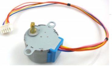 Were going to fire just a single phase at a time; this is probably the simplest method but its likely the least used because the other two methods have some advantages but with wave driving again were only going to fire a single phase at a time, so if I look through this diagram on the top in any one time slice so with step one just the blue phases energized then just the pink phase then just the yellow then just the orange so theres really four phases in this cycle here and then I just repeat blue-pink-yellow-orange; Lets now have a little practice:) Use your ULN2003 BOARD this way: Please see this post for more information: Full stepping is going to give me the same step angle as wave driving so Im going to get the same precision with the full step as I do with wave drive but Im going to get double the torque because with full stepping were actually going to energize two phases at a time so at any one given time slice; here two phases are energized; first the blue and the pink then the pink and the yellow then the yellow and orange then the blue and the orange; so thats a single cycle through those four phases and then again I repeat blue and pink yellow pink yellow orange orange and blue.
- Pandora 3 Flower Earrings
- Black And Decker Lst300 Type 2 Parts
- Extech Dl160 Software
- Best 30 Oz Tumbler Heat Press
- Fruity Pebbles Protein Powder Gnc